FM transmitter circuit
The proposed circuit is straightforward to build an FM transmitter with a range of 5 km. Includes 3 stages. Modulator / Oscillator, 500mW 2-phase amplifier. The circuit enables the transmission of music signals to the FM band at frequencies from 88MHz to 108MHz.
As a result of surprisingly low power usage of less than 100mA, the circuit can be operated flawlessly by applying a 9-12V battery or power source if you choose. The circuit can be divided into individual stages so that it is helpful for everyone to understand how each individual part works.
First stage
Used items
C1_ 4,7 uf
C2 C3 _470 pf
C4_2 pf
C5_30 pf timer
C6_ 2 pf
R1 R2_ 10khm
R3_ 100 ohm
TR 1_ BC549 _BC548_ BC547_S9018_S9014_2N2222
Lm7805 voltage regulator - or any other voltage regulator
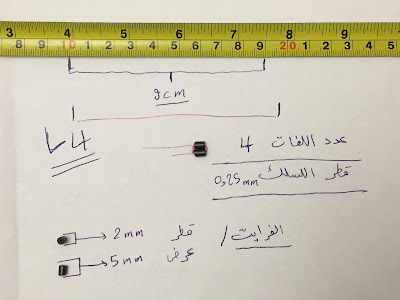
L1 A copper or silver wire of 1 mm diameter is wrapped around a cylinder of 5 mm diameter and 1 cm width of coil. As shown in the pictures below.
منظم الجهد
The second phase
The components of this phase
C8 variable capacitor 30 pf
C9 variable capacitor 30 pf
C10 ceramic capacitor 1 nf code {102}
C11 Ceramic Capacitor 100 nf Code {104}
C12 chemical capacitor 47 uf
C13 ceramic capacitor 22 pf code {22}
TR2_ BC549 _BC548_ BC547_S9018_S9014_2N2222
The L2 coil
Number of turns 4 The length of the wire is 12 cm, the diameter of the coil is 9 mm, the width of the coil, the distance between its ends is 6 mm, the thickness of the wire is 1 mm.
Tags
FM Radio


